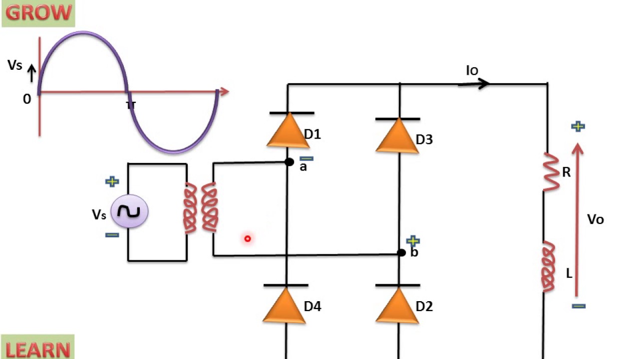
Diode Bridge Circuit Diagram
[get 44+] diode bridge rectifier circuit diagram Basic electronics : diode bridge How does a 4 diode bridge rectifier work
How to make 24v adapter or DC power supply easy at home
Diode bridge rectifier diagram Full wave rectifier bridge type How does a diode work in an ac circuit » wiring core
Full bridge rectifier circuit diagram
Comment brancher un pont de diodeHow to select free wheeling diode Full wave bridge rectifier with capacitor filter design pcb circuitsFull wave bridge rectifier circuit diagram.
Diode redresseur circuit pont rectifier lm324 diodes tension zpag electroniques fonctionnement allez apprendre aopBridge rectifier circuit diagram Diode 24vBridge rectifier circuit diagram and waveform.
![How to make 24v adapter or DC power supply easy at home](https://1.bp.blogspot.com/-pKT7KFZueJM/XWc1R8QlZMI/AAAAAAAABcg/iojylEJFnPUvhUFSGIn2Nl2PVekZa3LLwCLcBGAs/s1600/diode-bridge-circuit-diagram.gif)
Un circuit redresseur avec pont de diodes lm324
Full wave rectifier graphRectifier circuit circuits using wave alternating relay convert Simple bridge rectifier circuitWhat is bridge rectifier? working, circuit diagram & waveforms.
Three-phase bridge diode rectifier with a high inductive electricalBridge diode circuit diagram Single phase full wave rectifier circuit diagramDiode rectifier electrical4u.
![How Does A 4 Diode Bridge Rectifier Work](https://i2.wp.com/upload.wikimedia.org/wikipedia/commons/0/0b/4_Diode_Bridge_Rectifier.png)
Ac rectifier circuit diagram
Full wave bridge rectifier – circuit diagram and working principleDiode bridge rectifier Rectifier tube circuit bridge amp diode amplifier crystal seekic audio diagramBridge rectifier circuit explained.
The full-wave bridge rectifierHow to make 24v adapter or dc power supply easy at home Crystal diode bridge rectifier circuit (for tube amp)Full wave rectifier schematic.
![Comment Brancher Un Pont De Diode | AUTOMASITES](https://i2.wp.com/lambdageeks.com/wp-content/uploads/2021/05/1920px-Diode_bridge_alt_1.svg-1536x640.png)
![BASIC ELECTRONICS : Diode Bridge](https://i2.wp.com/www.derf.com/wp-content/uploads/2020/09/Figure-2.png)
![Ac Rectifier Circuit Diagram](https://i2.wp.com/electronicsreference.com/wp-content/uploads/2021/03/Schematic-diagram-2-1024x395.gif)
![Full Wave Bridge Rectifier Circuit Diagram - Riset](https://i2.wp.com/circuitglobe.com/wp-content/uploads/2015/12/FULL-WAVE-BRIDGE-RECTIFIER-FIG-1-compressor.jpg)
![[Get 44+] Diode Bridge Rectifier Circuit Diagram](https://i.ytimg.com/vi/p5DLEpDRBYk/maxresdefault.jpg)
![Full Wave Bridge Rectifier – Circuit Diagram and Working Principle](https://i2.wp.com/www.electroduino.com/wp-content/uploads/2021/04/Full-Wave-Bridge-Rectifier-–-Circuit-Diagram-and-Working-Principle.jpg)
![Un circuit redresseur avec pont de diodes LM324](https://i2.wp.com/www.zpag.net/Electroniques/AOP/Images/img5C.jpg)
![Crystal Diode Bridge Rectifier Circuit (For Tube Amp) - Tube_Amplifier](https://i2.wp.com/www.seekic.com/uploadfile/ic-circuit/201171721263752.gif)
![Full Wave Bridge Rectifier With Capacitor Filter Design Pcb Circuits](https://i2.wp.com/electric-shocks.com/wp-content/uploads/2019/06/Full-Bridge-Rectifier-Current-Flow-during-positive-Half-Cycle.jpg)
![Single Phase Full Wave Rectifier Circuit Diagram](https://i.ytimg.com/vi/Ry6FHj8EuVY/maxresdefault.jpg)